Alien 560 Quadcopter Build - Part 2 - Assembly
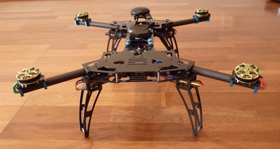
Unlike a conventional helicopter, a multirotor aircraft contains very few moving parts: no gears, no swash plates, no contrarotating propellers. It only has motors directly driving propellers, and that’s it. So there was no complex mechanics to assemble. The frame was probably the most complicated bit. The Alien 560 frame consists of a couple of dozen carbon fibre plates which need to be screwed together by a hundred or so tiny screws.
The assembly instruction was not included in the kit, but it can be downloaded from here. In the end, it is not much complex than a large Meccano set. I found that placing a magnetic mat or tray under the frame during the assembly reduces the chances of losing those little screws. I also put a medium-strength thread lock on the screws which are prone to loosening from vibration, such as motor mounts. I held off attaching the upper deck (the frame’s lid) for now; that would wait till all the cables are in place.
The next step was to assemble the power system. The Pixhawk comes with a power module which sits between the battery and the rest of the electrical parts and provides power to the flight controller. A power distribution harness plugs into the other side of the power module and distributes the power to the 4 ESCs (electronic speed controllers). The Alien frame has compartments in the landing gear’s “legs” for mounting ESCs - that position provides optimal cooling during flight. Because the power harness’s wires were too short to reach the ESC bays, I had to make the extender leads out of 16AWG wires and bullet connectors. The ESCs then feed power to the motors positioned at the ends of the foldable “arms” (more extension power leads were necessary here). I insulated all the electrical connection points with shrink-wraps to avoid short circuits. The power fed to each motor can reach 10A, so you definitely don’t want that to happen.
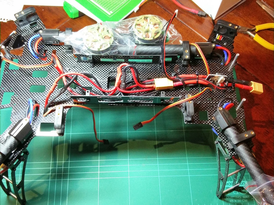
That was it for the power circuits. The next step was to assemble the signal chains.
First, the receiver. I used an FRSky X8R receiver. It is a good idea to pair your receiver to the transmitter before installing it. The included FRSky manual describes the steps to do that, and there are plenty of videos on Youtube showing the process.
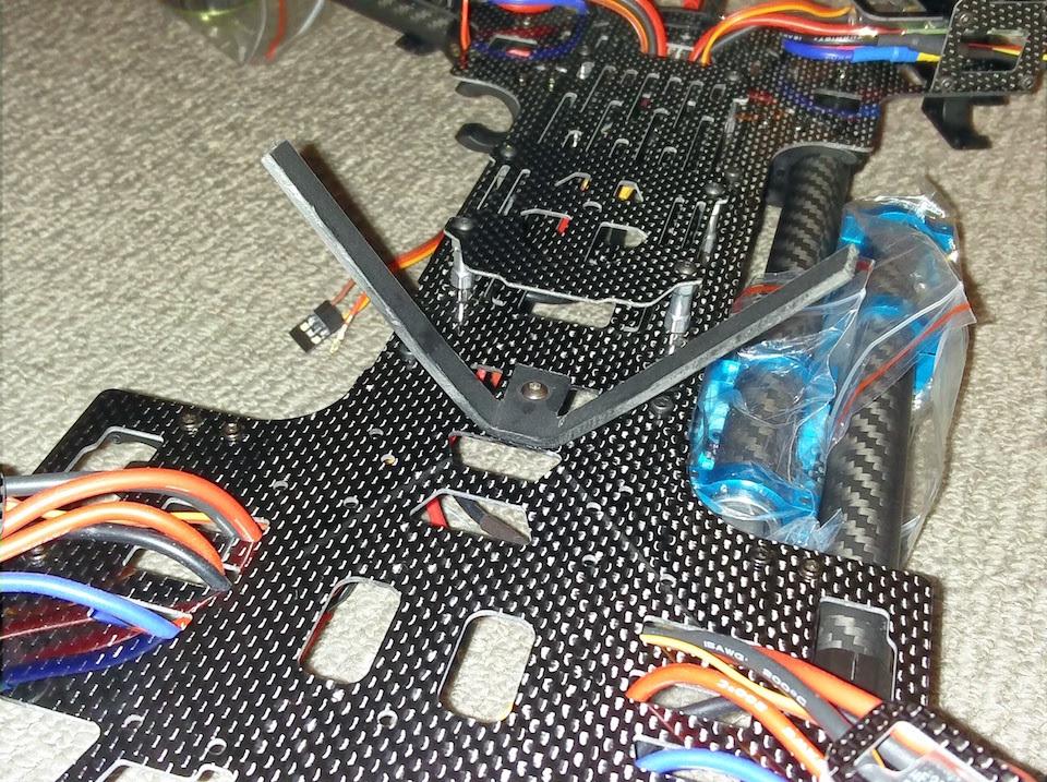
FRSky X8R receiver has two diversity antennas, and it chooses the one with the strongest signal during the operation. FRSky recommends putting the antennas apart at 90 degrees angle to each other. I made an antenna mount out of a piece of plastic, drilled the hole in the frame and mounted the antennas so that they pointed downwards. Then mounted the receiver on the lower deck attached by a piece of a double-sided sticky tape.
I can’t stress enough that an utmost care must be taken while working with carbon fibre. Carbon fibre dust is extremely harmful. Therefore any drilling or sanding carbon fibre must be carried out in a well-ventilated area, and a respirator with N95 safety rating must be worn.{.text-danger}
There are multiple ways to plug a receiver into Pixhawk. The serial SBus interface both Pixhawk and FRSky support is the easiest option. It allows connecting the receiver to the flight controller via a single cable rather than one for each channel. This page describes how to make the connection.
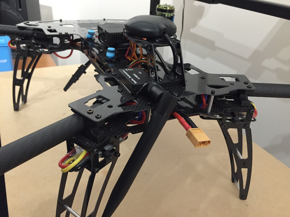
The GPS receiver has to be mounted on the top of the aircraft away from any sources of interference such as battery and motors. And because Neo-M8N GPS module I used also had a compass in it, it had to be oriented the right way forward. The best way to mount a GPS module on a quadcopter is to lift it above the deck on a mast. But the Alien frame had an elevated GPS mount plate which I decided to use. By design, it would be sitting at the far back of the aircraft, like a scorpion’s tail, but because my GPS cable was short, I moved it closer to the centre and rotated 180 degrees.
The next step was to connect the GPS and the telemetry. And that was where Pixhawk Lite played a joke on me. The wiring of all the Pixhawk modules is spelt out in the Adrupilot Wiki. If you buy all the electronic components such as GSP, telemetry, and OSD in a package then connecting them together should be as easy as plugging the appropriate wires. But Pixhawk Lite’s designers committed a few mistakes when laying out the controller’s connectors. Therefore some of the signal leads had to be rewired. These are the bits which had to be changed (extracted from the rcgroups forum’s thread mentioned above and Banggood comments:
-
GPS Cable Changes Required: The 5V and GND wires are reversed. The RX and TX lines of the GPS are connected to the telemetry lines etc. So they need to be directly moved by two pins towards the new 5V line.
-
Telemetry Cable Changes Required: The 5V and GND wires are also reversed. The RX and TX also need to be swapped, but the lines stay in their current pins.
-
Although the wiring of the power connector is compatible with the included power module, the standard Pixhawk’s power module cannot be used because of the wiring changes.
After carefully rewiring the connectors I was finally able to plug the modules together.
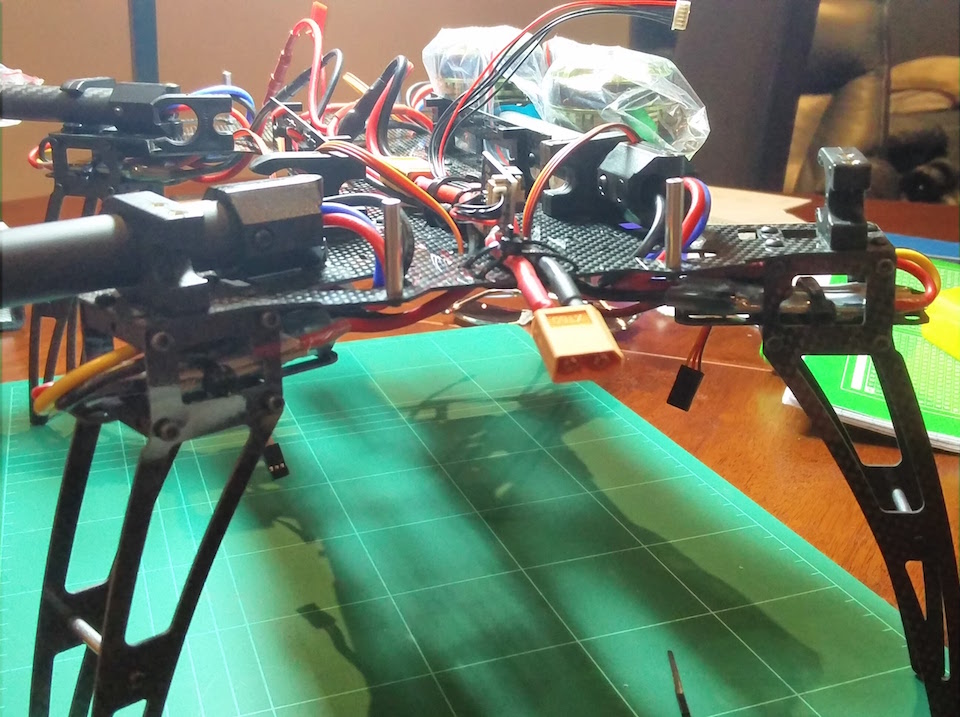
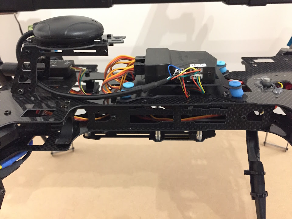
I wanted to mount the telemetry transmitter with its antenna facing down for a better signal. But the problem was that telemetry antenna was huge compared to the rest of the components. Its size was dictated by the frequency is used, which was 915 Mhz - the frequency allowed in Australia. That made the antenna as large as a one of a Wi-Fi router. I decided to place the telemetry receiver at the back on the upper deck with its antenna strapped to one of the rear landing gear. That would keep it secure and out of reach of the spinning propellers. The antenna’s weight at the back will also counteract the weight of a camera in front should I decide to install one later.
Pixhawk has an external reset button which I glued to the upper deck with a drop of hot glue.
The last thing to install was the flight controller itself. As prescribed by the Pixhawk’s designers, it should be mounted at the centre of an aircraft on an anti-vibration pad. High-frequency vibrations produced by spinning motors interfere with the Pixhawk’s built-in gyroscopes jeopardising the flight stability. There are many different ways to dampen the vibration. A genuine 3DR Pixhawk, for example, comes with a few pieces of a 3M double-sided foam. Also, copter builders through experimentation discovered a few more efficient ways. I decided to go with an anti-vibration mount consisting of two plates with rubber bushings in between which was similar to the highly recommended 3D printed mount. I fastened the dampening mount to the upper deck with a couple of screws and attached the Pixhawk Lite to it with a servo tape.
Now was the time to secure the top upper deck to the rest of the frame with the remaining screws from the frame kit and to plug all the signal cables into the flight controller: GPS, compass, telemetry, receiver and ESCs. The four ESCs are plugged into Pixhawk’s servo channels 1 - 4 strictly according to the aircraft’s configuration. An important note is that although Pixhawk servo connectors have +5V pin, Pixhawk doesn’t provide +5V power to the servo rail. Considering that in our build the Pixhawk is powered from its power module rather than a servo rail (that configuration is also possible), it makes sense to disconnect +5V (red) wire from the ESC connectors before plugging them in. That is because +5V from the power module may not have the exact same potential as +5V from the ESCs, and that can create a harmful voltage differential.
Finally, I had everything installed and plugged in. The next step would be to set up the software.
To be continued…