A flight controller is the brain of any multirotor; it is the most crucial component. When my Alien 560 quadcopterfell from the sky, I figured it happened because its flight controller malfunctioned mid-flight. Therefore, when I decided to build a new drone and started choosing the components, a flight controller was the most difficult choice to make.
About a year ago Hobbyking was having one of their “Flash Sale” events. During a few days, they dropped prices on a few hundred items. An online shopaholic in me couldn’t miss it. I meticulously studied the offerings until I found something worthy of my attention and money. That was a Jumper 218 Pro racing quadcopter, almost ready to run. A bargain at a just a bit over $100! I just needed to add an RC receiver.
I received it a few days later and, as it often happens, put it on a shelf for a few months. From time to time I would take it off the shelf, hold it in my hands, make a few plans for it, and then put it back. At the time I was still concentrating on building my Alien 560 quadcopter, and the smaller drone was a distraction. The “project Alien” appeared to be never-ending. Every time I flew it, I saw a way to improve it. I would disassemble the copter and work on it for a week or two. Then put it back together, fly it, and then dismantle again. Only when I crashed the Alien, I decided to take a break from it and turned my attention to the Jumper.
I wish I could tell you that setting up the transmitter was straightforward, but unfortunately, it wasn’t. I’ll do my best to describe what I did, although I’m not sure my process is 100% repeatable.
I have a Turnigy 9XR Pro transmitter with a FrSky JR module. It is a digital radio with lots of features: updateable firmware, model memory, custom sound files and so on.
The first thing I did was upgrading the firmware. That process is a bit different depending on whether you have a PC or Mac. Effectively it involves connecting the transmitter to the PC with a USB cable, firing up eepskye application, setting a few parameters and flashing a new firmware via the app. I found a useful cheatsheet for updating Turnigy 9XR firmware at Quadcopter Basics website. It is also worth to consult the official Turnigy 9XR Pro: Using the Eepskye Program manual.
All subsequent setup is performed on the transmitter itself via the series of the menus. Unfortunately, the structure of those menus changes depending on the firmware version. My version after the upgrade was V.3527-Mike. There’s a 9xr tutorials RCGroups forum thread to help you with the initial setup, besides John G provided a useful Turnigy 9XR APM Arducopter/Arduplane radio settings cheatsheet. Also don’t neglect to check the official 9XR Pro: First Steps with Ersky9x manual, but keep in mind that those may be outdated.
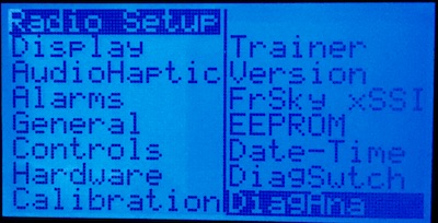
A long press on the left side 4-position switch gets you to the main menu.
Go into Controls to change the channel order. Pixhawk requires the channels to be in AETR order: Aileron, Elevator, Throttle, Rudder. However, although that is a correct order for Mode 2 radio I have, the order may be different for Mode 1.
In Calibration section calibrate the radio’s controls.
Set current date and time in Date-Time section.
Exit returns you to the main screen.
A long press on the right side 4-position switch gets you to the main menu. Here you need to create a new entry for your model.
Once you create a new model name, there are a few settings which need to be set up for it.
First of all, Enter Protocol section to set up your module and receiver options:
In my case, the protocol needs to be set to PXX which FrSky uses.
RxNum is 1 which is the number of the paired receiver in that model.
Type is D16 - the receiver is configured for 16 channels (check your receiver manual, for FrSky X8R I use it is a default configuration with no jumpers shortened.
Finally, pressing Bind puts the transmitter module into bind mode. Follow your receiver manual to bind the transmitter to the receiver. For X8R it involves just pressing a Bind button on the receiver once the transmitter is in bind mode.
Setting up flight modes
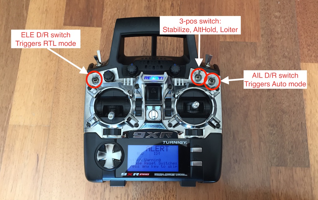
Pixhawk has quite a few flight modes. If you want to switch flight modes in-flight, a radio transmitter usually has a 3-way switch you can use (some radios have a 6-way switch). Turnigy 9XR has a 3-way switch, but I wanted to do something more advanced than just being able to choose between 3 modes. I got an idea from Mike Perillo’s blog post. My setup allows me to switch between 5 modes in the following way:
ELE D/R switch on the left is mapped to RTL(Return-to-Launch) mode. If it is turned on, it overrides all the other mode settings. It is an emergency feature aimed to return the aircraft to the launch site with a single switch flip.
AIL D/R switch on the right is mapped to Auto mode and overrides other mode settings except for RTL switch.
The 3-way switch is mapped to Stabilize, Alt Hold, and Loiter, but only if RTL or Auto are not enabled.
The way I did that was with the combination of logical switches and mixer configuration. An important thing to understand is that the flight channels are mapped to the values on Channel 5 according to the configuration you define in Mission Planner or QGroundCtrl (more on that later). So all you need to do is to map different flight modes to values evenly spread across -100 … +100 range on channel 5. That involves a few steps:
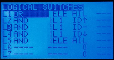
Enter Model Setup → L.Switches menu. Logical switches can have On and Off values just like real switches, but they are defined by logical formulas rather than positions of the handles on the transmitter. Set up logical switches like this:
This effectively corresponds to the following formulas:
L1 = ELE OR AIL. Logical switch L1 is enabled if either ELE D/R or AIL D/R switch is on. In other words, if L1 is off when neither RTL nor Auto mode is engaged.
L2 = (NOT L1) AND ID-UP, L3 = (NOT L1) AND ID-CENTRE, L3 = (NOT L1) AND ID-DOWN. That means that L2 - L4 switches will only take effect if L1 is off, i.e. when neither RTL nor Auto mode is engaged. Logical switches L2 - L4 will be responsible for Stabilize, Alt Hold, and Loiter modes respectively depending on the position of the 3-wat switch (up, centre, or down).
L5 = (NOT ELE) AND AIL. Logical switch L5 is responsible for Auto mode and will only be enabled when ELE D/R switch is off and AIL D/R switch is on.
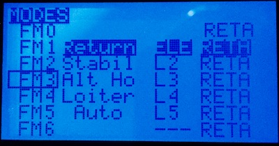
Next set up flight modes in Modes menu.
You can see that Flight Mode 1 - Return is triggered by ELE D/R switch, while 4 other modes: Stabil, Alt Ho(ld), Loiter, and Auto are triggered by logical switches L2 to L5 respectively.
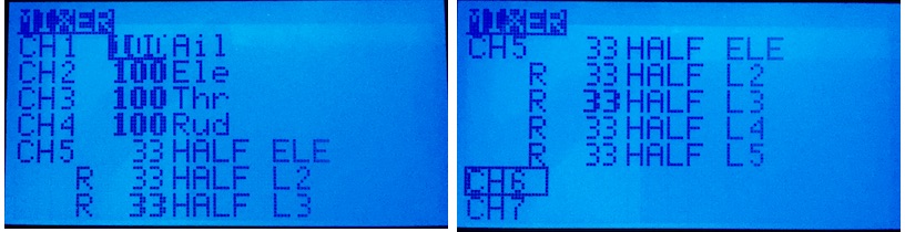
And finally, enter Mixer menu. These are probably the most complex settings in the entire transmitter, and I’m going to cover just enough of it to set up the flight modes the way we want.
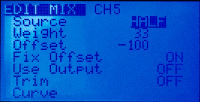
You can see that channels 1 to 4 are mapped 100% to Aileron, Elevator, Throttle, Rudder (remember I told you about AERT channel order?), while channel 5 is different. It is configured to trigger the discrete values depending on the values of the switches we have previously set up. All the CH5 submixes are identical except for Offset and Switch values.
1st: has Weight: 33, Offset: -100, and Switch: ELE
2nd: Weight: 33, Offset: -77, and Switch: L2
3rd: Weight: 33, Offset: -50, and Switch: L3
4th: Weight: 33, Offset: -20, and Switch: L4
5rd: Weight: 33, Offset: 27, and Switch: L5
Submixes 2-5 have Replace multiplier. The above setup means that switches ELE, L2, L3, L4 and L5 are mapped to values -100, -77, -50, -20, 27 on channel 5 axis, which works nicely to switch between the first 5 channels configured in the ground station software (I’ll cover that later). I chose those values empirically by tweaking them until that worked.
That concludes the transmitter setup. Next, to the Pixhawk software setup and configuration.
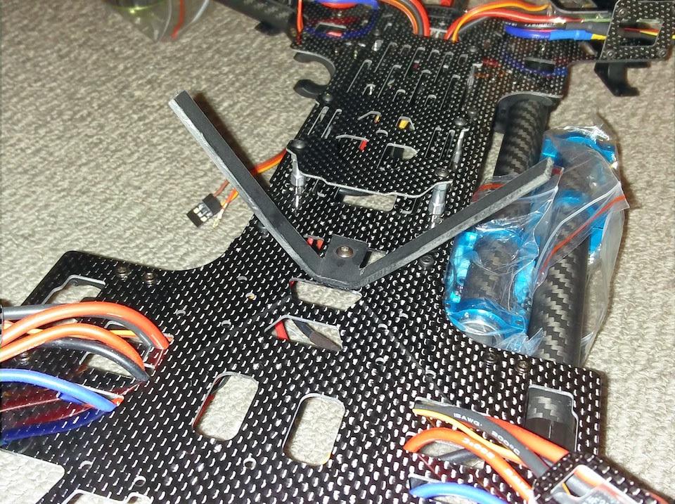
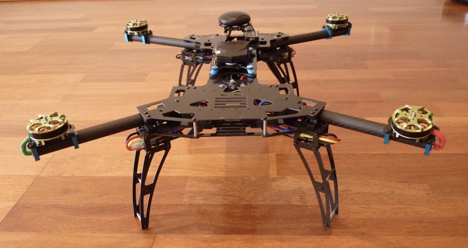
Unlike a conventional helicopter, a multirotor aircraft contains very few moving parts: no gears, no swash plates, no contrarotating propellers. It only has motors directly driving propellers, and that’s it. So there was no complex mechanics to assemble. The frame was probably the most complicated bit. The Alien 560 frame consists of a couple of dozen carbon fibre plates which need to be screwed together by a hundred or so tiny screws.
The assembly instruction was not included in the kit, but it can be downloaded from here. In the end, it is not much complex than a large Meccano set. I found that placing a magnetic mat or tray under the frame during the assembly reduces the chances of losing those little screws. I also put a medium-strength thread lock on the screws which are prone to loosening from vibration, such as motor mounts. I held off attaching the upper deck (the frame’s lid) for now; that would wait till all the cables are in place.
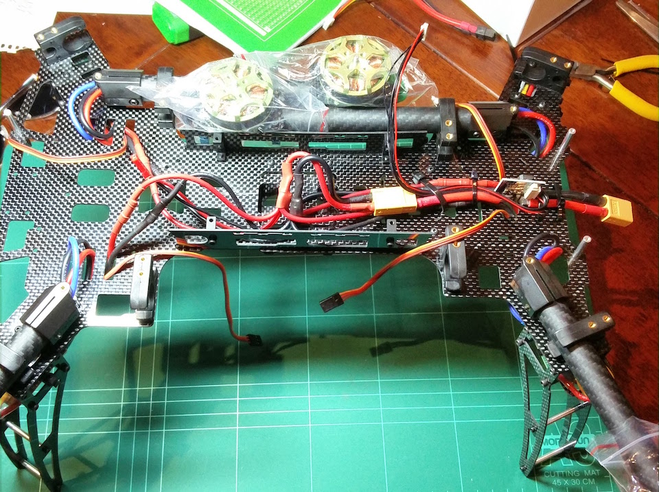
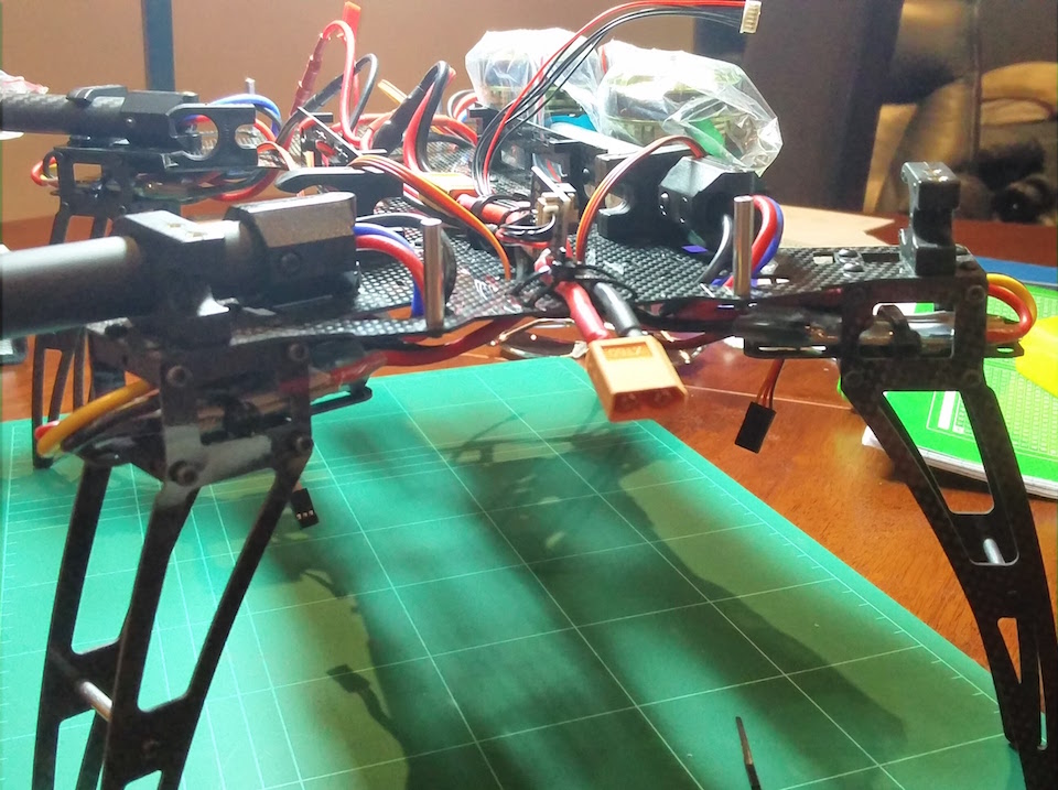
The next step was to assemble the power system. The Pixhawk comes with a power module which sits between the battery and the rest of the electrical parts and provides power to the flight controller. A power distribution harness plugs into the other side of the power module and distributes the power to the 4 ESCs(electronic speed controllers). The Alien frame has compartments in the landing gear’s “legs” for mounting ESCs - that position provides optimal cooling during flight. Because the power harness’s wires were too short to reach the ESC bays, I had to make the extender leads out of 16AWG wires and bullet connectors. The ESCs then feed power to the motors positioned at the ends of the foldable “arms” (more extension power leads were necessary here). I insulated all the electrical connection points with shrink-wraps to avoid short circuits. The power fed to each motor can reach 10A, so you definitely don’t want that to happen.
That was it for the power circuits. The next step was to assemble the signal chains.
First, the receiver. I used an FRSky X8R receiver. It is a good idea to pair your receiver to the transmitter before installing it. The included FRSky manual describes the steps to do that, and there are plenty of videos on Youtube showing the process.
FRSky X8R receiver has two diversity antennas, and it chooses the one with the strongest signal during the operation. FRSky recommends putting the antennas apart at 90 degrees angle to each other. I made an antenna mount out of a piece of plastic, drilled the hole in the frame and mounted the antennas so that they pointed downwards. Then mounted the receiver on the lower deck attached by a piece of a double-sided sticky tape.
I can’t stress enough that an utmost care must be taken while working with carbon fibre. Carbon fibre dust is extremely harmful. Therefore any drilling or sanding carbon fibre must be carried out in a well-ventilated area, and a respirator with N95 safety rating must be worn.{.text-danger}
There are multiple ways to plug a receiver into Pixhawk. The serial SBus interface both Pixhawk and FRSky support is the easiest option. It allows connecting the receiver to the flight controller via a single cable rather than one for each channel. This page describes how to make the connection.
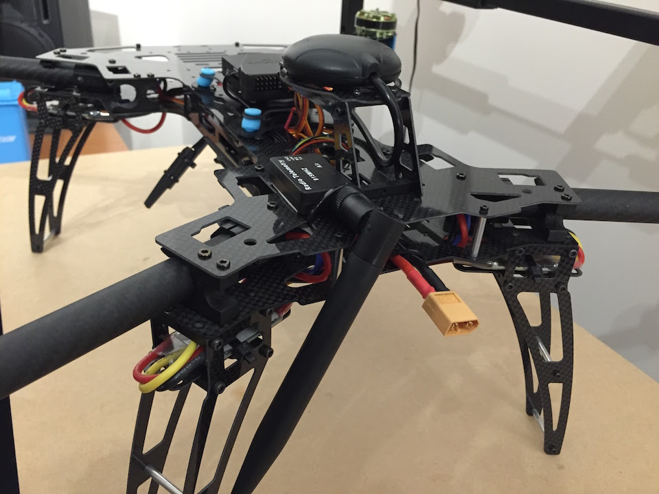
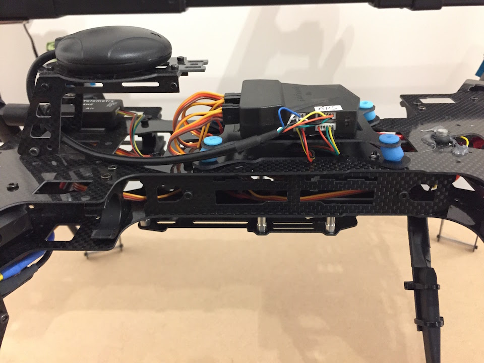
The GPS receiver has to be mounted on the top of the aircraft away from any sources of interference such as battery and motors. And because Neo-M8N GPS module I used also had a compass in it, it had to be oriented the right way forward. The best way to mount a GPS module on a quadcopter is to lift it above the deck on a mast. But the Alien frame had an elevated GPS mount plate which I decided to use. By design, it would be sitting at the far back of the aircraft, like a scorpion’s tail, but because my GPS cable was short, I moved it closer to the centre and rotated 180 degrees.
The next step was to connect the GPS and the telemetry. And that was where Pixhawk Lite played a joke on me. The wiring of all the Pixhawk modules is spelt out in the Adrupilot Wiki. If you buy all the electronic components such as GSP, telemetry, and OSD in a package then connecting them together should be as easy as plugging the appropriate wires. But Pixhawk Lite’s designers committed a few mistakes when laying out the controller’s connectors. Therefore some of the signal leads had to be rewired. These are the bits which had to be changed (extracted from the rcgroups forum’s thread mentioned above and Banggood comments:
GPS Cable Changes Required: The 5V and GND wires are reversed. The RX and TX lines of the GPS are connected to the telemetry lines etc. So they need to be directly moved by two pins towards the new 5V line.
Telemetry Cable Changes Required: The 5V and GND wires are also reversed. The RX and TX also need to be swapped, but the lines stay in their current pins.
Although the wiring of the power connector is compatible with the included power module, the standard Pixhawk’s power module cannot be used because of the wiring changes.
After carefully rewiring the connectors I was finally able to plug the modules together.
I wanted to mount the telemetry transmitter with its antenna facing down for a better signal. But the problem was that telemetry antenna was huge compared to the rest of the components. Its size was dictated by the frequency is used, which was 915 Mhz - the frequency allowed in Australia. That made the antenna as large as a one of a Wi-Fi router. I decided to place the telemetry receiver at the back on the upper deck with its antenna strapped to one of the rear landing gear. That would keep it secure and out of reach of the spinning propellers. The antenna’s weight at the back will also counteract the weight of a camera in front should I decide to install one later.
Pixhawk has an external reset button which I glued to the upper deck with a drop of hot glue.
The last thing to install was the flight controller itself. As prescribed by the Pixhawk’s designers, it should be mounted at the centre of an aircraft on an anti-vibration pad. High-frequency vibrations produced by spinning motors interfere with the Pixhawk’s built-in gyroscopes jeopardising the flight stability. There are many different ways to dampen the vibration. A genuine 3DR Pixhawk, for example, comes with a few pieces of a 3M double-sided foam. Also, copter builders through experimentation discovered a few more efficient ways. I decided to go with an anti-vibration mount consisting of two plates with rubber bushings in between which was similar to the highly recommended 3D printed mount. I fastened the dampening mount to the upper deck with a couple of screws and attached the Pixhawk Lite to it with a servo tape.
Now was the time to secure the top upper deck to the rest of the frame with the remaining screws from the frame kit and to plug all the signal cables into the flight controller: GPS, compass, telemetry, receiver and ESCs. The four ESCs are plugged into Pixhawk’s servo channels 1 - 4 strictly according to the aircraft’s configuration. An important note is that although Pixhawk servo connectors have +5V pin, Pixhawk doesn’t provide +5V power to the servo rail. Considering that in our build the Pixhawk is powered from its power module rather than a servo rail (that configuration is also possible), it makes sense to disconnect +5V (red) wire from the ESC connectors before plugging them in. That is because +5V from the power module may not have the exact same potential as +5V from the ESCs, and that can create a harmful voltage differential.
Finally, I had everything installed and plugged in. The next step would be to set up the software.